Challenges for LEO HTS Megaconstelllations: Terrestrial Networks Integration
by Muhammad Furqan and Waheeb Butt
Brisbane, Australia, October 4, 2020--By now, we all are aware of the magnitude of the 1st generation of NGSO (Non-Geo Stationary Orbit) mega constellation and their capabilities for provision of high throughput, low latency, global broadband to everyone, everywhere. Let us move forward and analyse the integration of the networks established by these constellations with already existing and upcoming terrestrial networks.
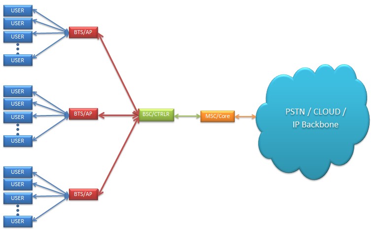 |
| Network Architecture for a Typical MNO/ISP Network |
Satellite communication has been serving the terrestrial network as a complementor rather than a competitor for a considerable time. The best use-case scenario is the cellular backhaul over VSAT (Very Small Aperture Terminal) to connect remotely installed BTS (Base Transceiver Station) of a cellular network through a geostationary satellite to the respective BSC (Base Station Controller) and ultimately the core network. This technology enabled MNOs (Mobile Network Operators) to increase their subscribers base in remote communities which could not be connected to their network grid through Microwave or Fibre transmission. Similar network architecture, commonly known as bent-pipe and FSS (Fixed Satellite Service), has been used by other networks requirements of ISP (Internet Service Providers), Government, Corporate, Oil & Gas, Mining sectors, where the DCE (Data Communication Equipment) and DTE (Data Terminal Equipment) are replaced from BTS and BSC to networking switches and routers.
However, all these communications are struggling to keep at par with development at terrestrial networks, and the main reason is staggering latency of around 530 milliseconds for a roundtrip of a message through the satellites at an altitude of around 37,000 kilometres, which is a big challenge for Industry 4.0 technologies. The arrival of the planned NGSO mega constellation appears to address the problem through claimed significantly lower latency of around 4 milliseconds, which is at par with fibre optics.
The integration of the networks of mega constellations with those on the ground is a complicated situation with multiple dynamics to analyse. Let us have a brief look at 4G LTE and 5G NR technology and analyse the integration for both backhaul and fronthaul interfaces through NGSO satellites with the core networks.
The development of cellular communication system has changed its course from being a national or regional concern to becoming an increasingly complex task undertaken by global standards-developing organizations such as the 3GPP (Third Generation partnership Project) and ITU (International Telecommunication Union). The constituent mobile communication technologies of the cellular communication system have evolved through different generations (G). Earlier during the 2G era and the initial deployment of 3G systems, the data traffic was at a notably low level even the introduction of packet data solutions, such as GPRS (General Packet Radio Service) and EDGE (Enhanced Data Rates for Global Evolution), was not able to increase the data services considerably. However, higher data rates, increased throughput and lower latency has significantly increased the use of packet data. LTE/LTE-A (Long Term Evolution/ Long Term Evolution-Advanced) guarantees the combined user and signalling data for the provision of a sufficiently smooth user experience especially in delay-critical applications like video conferencing and real-time gaming etc. LTE-A extends the 20 MHz bandwidth of basic LTE up to 100 MHz which in turn increases the theoretical data rate 200 Mb/s of LTE up to 1 – 3 Gb/s based on the set of functionalities.[1].
According to 3GPP, the key features associated with LTE/LTE-A are:
• High spectral efficiency. OFDM (Orthogonal Frequency Division Multiplexing) is used in the downlink transmission to make the system more robust against multipath interference with the help of frequency domain channel-dependent scheduling and MIMO (Multiple Input Multiple Output) systems whereas DFTS-OFDM (Discrete Fourier Transform Spread-OFDM) and SC-FDMA (Single-Carrier Frequency Division Multiple Access) are used in the uplink along with the multi-antenna approach transmission in order to provide a low PAPR (Peak-to-Average Power ratio).
• Very Low Latency. In addition to keeping the TTI (Transmission Time Interval) and RRC (Radio Resource Control) procedure short, handover latency, transfer delay and interruption time are kept considerably short as well for the desired low latency rate.
• Simple Architecture. The introduction of eNodeB as the only node in E-UTRAN (Evolved-UMTS Radio Access Network) lead to smaller number of RAN (Radio Access Network) interfaces, X2 and S1.
The connection between different eNodeB elements is established by the X2 interface which is meant for eNodeB handover procedures, data forwarding as well as interference management of the RRM (Radio Resource Management). The S1 interface is used to establish the connection between the eNodeB and the EPC (Evolved Packet Core), it is further divided into S1-MME and S1-U. S1-MME connects the eNodeB to the MME (Mobility Management Entity) and S1-U connects the eNodeB to the S-GW (Serving Gateway).
The core network of LTE-A is designed on the same principles as that of LTE in order to avoid any bottlenecks due to the increased data rates.
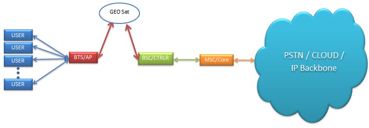 |
| VSAT Network Architecture |
Furthermore, the backhaul portions are to be dimensioned in such a way that they do not create bottlenecks as well. Considering the maximum and average data rate of the radio interface, the core dimensioning is balanced in such a way that the core network is neither over-dimensioned (increased operational cost) nor under-dimensioned (loss of revenue and customer dissatisfaction). The infrastructure of 2G and 3G TDM (Time Division Multiplexing) backhauling still needs to be supported, therefore, in order to support both the lower data rate systems and the high data rates of LTE/LTE-A, it requires high scalability from the IP (Internet Protocol) core and backhaul networks. Preferably, backhauling is performed via fibre optics or microwave radio links between the base station and the radio controller whereas the traditional solution has been the circuit-switched TDM, nevertheless the transition to the all-IP concept in supporting stages of the core network is obvious.
The deployment of LTE/LTE-A along with the re-usage of existing physical sites requires sufficient scalability of the backhaul network in order to meet all the system capacity demands of the site. Thus, the backhaul needs to support the traffic of multiple technologies such as TDM and Ethernet/IP while maintaining control for the QoS (Quality of Service), therefore the dimensioning of the core network should be based on the probable distribution of the services; ensuring that the QoS meets expectations for the most demanding services, such as real-time video.
The evolution of RAN topologies and the concept of hybrid architecture are mainly driven by new LTE-A features, such as eICIC (Enhanced Inter-Cell Interference Coordination) and CoMP (Coordinated Multipoint) over ideal and non-ideal backhaul. Ideal backhaul provides less than 2.5 µsec latency whereas non-ideal backhaul’s latency is in the range of 5-30 msec which can be even more in case of DSL (Digital Subscriber Line) or cable access. The backhaul networks are designed to support a multi-RAT (Radio Access Technology) macro layer and LTE-based small-cell layer. Practically speaking, hybrid backhaul/fronthaul architecture offers RAN capacity and/or performance benefits with the likelihood of a multi-RAT cell site having legacy services on the backhaul while migrating the LTE on C-RAN (Centralized-RAN) architecture which leads to hybrid transport mechanism such as CWDM (Coarse Wave Division Multiplexing), or hybrid wireless.
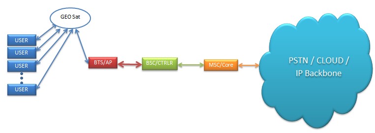 |
| MSS Network Architecture |
The requirement of minimum received power levels for certain data rates leads to the adoption of different access methods in the uplink and downlink transmissions. The received power level is dependent on the presence of useful and interfering signals compared to the noise level; SINR (Signal to Interference Noise Ratio) values indicating the QoS level. The fast fading environments (dense urban areas) with a high number of multipath propagation components, makes OFDMA as the most suitable choice for LTE downlink transmission but the associated drawbacks such as PAPR along with non-optimal power efficiency compels the UE (User Equipment) to use energy efficient SC-FDMA. The combination of OFDMA and SC-FDMA provides coverage areas comparable to HSPA (High Speed Packet Access) networks but offering high data rates. The functionality of the handovers plays an important role to ensure the QoS in all cases where LTE/LTE-A coverage area is sufficiently good. The X2 interface between the eNodeB elements optimizes the success rate of the handovers in LTE as compared to the previous techniques. In a probable situation of service outage, the LTE connection is changed automatically to 2G/3G networks affecting the QoS level as the overall data throughput will be lower in this case. This fall-back procedure could seriously impact some of the applications involving real time data streaming but it wouldn’t have the same effect for VoIP (Voice over IP) connection. Nevertheless, from the user point of view, the continuum of the service is more important even with reduced throughput rather than complete breakdown of the service.
ITU-defined 5G applications include eMBB (Enhanced Mobile Broadband), mMTC (massive Machine Type Communication) and uRLLC (Ultra Reliable Low Latency Communication). In all these deployment options, FWA (Fixed Wireless Access) is employed as a competitive substitute to FTTx (Fibre-to-the-x) owing to its superior radio capabilities and reduced operational cost, leading to an economically feasible broadband connectivity. FWA enables the mobile operators to meet the rising broadband demand with cheaper connectivity solutions rendering additional broadband revenue streams. Furthermore, FWA can provide a broadband upgrade in areas where xDSL or copper lines are hard to replace or if there is a time-limited demand.
Mainly, the deployment of 5G is either SA (Standalone) or NSA (Non-Standalone). SA option consists of only one generation of RAT whereas NSA consists of two generations of RAT (4G LTE and 5G). The NSA option leverages existing 4G deployment as the RAN is composed of eNodeBs as master node and gNodeBs as secondary node with a connection to EPC. In the SA deployment, RAN is composed of only gNodeBs and connects to 5GC (5G core). It does not have any impact on LTE radio and is capable of supporting all 5G use cases with network slicing via cloud native service-based architecture unlike NSA which may not be optimized for new 5G use cases beyond mobile broadband. The left and right side of the figure on the previous page represents the NSA and SA deployment options respectively [2].
In order to support NSA, the 4G core network needs only software upgrade without any modifications in the hardware since the handover procedure in 5G is not different from 4G network whereas EPC upgrade may be done under two scenarios. In the first scenario, the physical EPC is upgraded to support NSA and the capacity expansion is based on the physical EPC whereas in the second scenario, a new virtualized EPC is built to support NSA, with interoperability with the physical EPC and the capacity expansion is based on the virtualized EPC. The evolution to 5G SA would be carried out swiftly in the second scenario unlike the first scenario where the physical EPC based on a dedicated hardware cannot be used in a virtualized environment
C-Band is the primary band for 5G network, having a large bandwidth makes it perfectly suitable for 5G eMBB services. Due to the large downlink transmit power of the gNodeB, downlink coverage is better than uplink. The coverage of the C-Band downlink is similar to that of LTE 1800 MHz but when it comes to uplink, the user experience is affected due to limitation in the coverage causing bottlenecks in 5G deployment. So in order to address the issue of this limited uplink coverage, 3GPP Rel. 15 introduced two mechanisms namely NR-CA (New Radio-Carrier Aggregation) and SUL (Supplementary Uplink). The synchronization of 5G network is also an important aspect to avoid interference ensuring an efficient usage of the spectrum and a reduced network equipment cost. If 5G macro-cells networks are not synchronized, more than 25 MHz additional guard-band together with additional transceiver filters would be required.
Fronthaul implementation plays a significant role to attain low latency level required by 5G use cases, manage mobile data growth, provision of scalability in terms of RAN densification and future evolution towards cloud RAN. As for the interfaces, eCPRI (Enhanced Common Public Radio Interface) and O-RAN (Open Radio Access Network) seem to be the main candidate for RRU (Remote Radio Unit) and CU/DU (Centralized Unit/ Distributed Unit) with a bandwidth granularity of 25Gbits/s. So the main aim is to adopt a single interface, eCPRI, with defined jitter/latency requirements for both 4G and 5G networks.
The idea of sharing the network infrastructure in 4G is expected to retain its popularity and continue in the 5G era, where the networks will be densified even more as compared to 4G networks. Network sharing comes in many forms but mainly classified as Passive and Active infrastructure sharing. In passive infrastructure sharing non-electronic components such as power supply-management system, and backhaul transport networks are shared. Active infrastructure sharing involves the sharing of electronic infrastructure of the network including RAN (consists of antennas/transceivers, base stations, backhaul networks and controllers) and core network (Server and core network functionalities). Some of the listed benefits of network infrastructure sharing are cost reduction, environmental benefits, improved customer experience and coverage expansion. Apart from these advantages, there are some disadvantages associated with the network infrastructure sharing approach as it may lead to hindrance in competition among the MNOs (Mobile Network Operators), since it is inherently difficult to differentiate own network infrastructure against the sharing partners. Furthermore, sharing of an existing network architecture is challenging because an existing network has already been planned and designed based on specific operator requirements, so consolidating it further is likely to be difficult if any of the requirements are conflicted. Keeping this in mind, the network infrastructure sharing may be difficult to implement in NSA but it may be more feasible with SA where both radio access and core networks would be newly deployed considering that the operators will collaborate from the planning phase.
It is worth observing the leaked performance results of SpaceX Starlink broadband services [3] during the compilation of this article and results, thus far, can help us better understand the application of LEO-HTS Mega-Constellation services for fronthaul or backhaul connectivity of given 4G or 5G cellular communications.
• Latency: 21 ms.
• Download: 45.9 Mbits/s. (5.7 MB/s.)
• Download: 10.1 Mbits/s. (1.3 MB/s.)
For the results given above, LEO-HTS satellites can be easily adopted to fronthaul of a 4G LTE network as well as 5G NR, with exception of mission-critical services where uRLLC is not the primary requirement. For the best-case scenario of Starlink VLEO (Very Low Earth Orbit) ~ 350km altitude, the latency for a roundtrip can be around 2.34 ms, which is remarkable and significant improvement to that of a traditional GEO satellite.
However, these are just the analysis of provision of fronthaul and backhaul services to cellular networks from the space, a thorough research is still needed to make a business case where lots of other considerations have to be studied for such technology. The satellites of the constellations, with inclusion on-board processing must be made to serve the purpose as a cellular Access Point through software defined technologies like SDN (Software Defined Network), SDR (Software Defined Radio), NFV (Network Function Virtualization), O-RAN etc. to connect directly to the user equipment via OTA (Over-The-Air) interface, as well as frequency spectrum adoptability of user equipment, doppler effect (estimated velocity of these satellites is 9km/s), link-budget analysis etc., for a complete network architecture.
References:
[1] The LTE-Advanced Deployment Handbook; https://www.wiley.com/en-us/The+LTE+Advanced+Deployment+Handbook%3A+The+...
[2] 5G Implementation guidelines; https://www.gsma.com/futurenetworks/wp-content/uploads/2019/03/5G-Implementation-Guideline-v2.0-July-2019.pdf
[3] https://freenews.live/first-starlink-internet-speed-tests-published/?fbclid=IwAR2wCxE8EJPBVWS3xt2JncYIzzcvYxn5TCgIBpKyrxk22D0wRQTVxleKzws
---------------------------
 With around a decade of experience in the satellite communications industry, Muhammad Furqan is a renowned writer and analyst with multiple publications and keynote appearances at different international platforms. Currently based in Australia, he is working in research related to Radio Frequency Electromagnetic Spectrum for mobile and satellite communications at Queensland University of Technology. He can be reached at: info@muhammadfurqan.com
 Waheeb Butt received his B.S. degree in Electronics from IIU Pakistan in 2007and M.Sc. degree in Communication and signal processing from Newcastle University, UK in 2009. Since then, he has been involved in teaching and research activities related to the field of telecommunication. He is currently doing PhD at RWTH Aachen University Germany, in the area of wireless communications. He can be reached at:waheeb.butt@ice.rwth-aachen.de