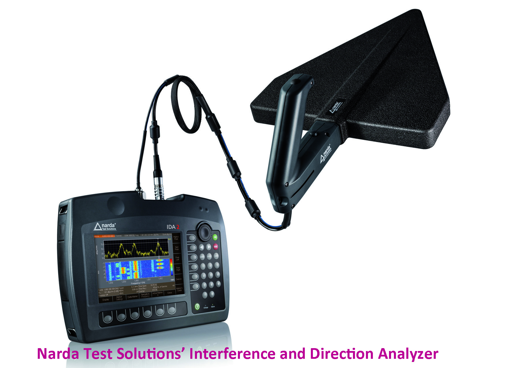
Handheld Direction Finder IDA 2 Detects Signals Under Signals

For this reason, Narda Safety Test Solutions has now equipped the Interference and Direction Analyzer IDA 2 with a Persistence Spectrum display mode, which shows the changing useful signals and the underlying interference signals at the same time. For example, interference beneath GSM downlink signals with their changing channel allocations or hidden under a DAB channel can be seen because it leaves traces in the persistence spectrum in the modulation gaps that correspond to the “null” symbols.
IDA 2 captures persistence spectrums with a usable bandwidth of up to 22 MHz. Various triggers can be set in order to capture brief events. Even unknown interferers can be “nailed”, thanks to the resolution bandwidth (RBW) down to 0.1 Hz, and time resolution as fine as 1 μs as the display of level characteristics versus time at up to 32 ns resolution.
Persistence Spectrum
The Persistence Spectrum display mode is based on the I/Q Analyzer operating mode. To produce a persistence spectrum, the IDA 2 writes a certain number of spectrums computed from a stored I/Q data set one on top of the other. The colors indicate how often a particular level value occurred. Persistence spectrums resemble the afterglow effect spectrums produced by older spectrum analyzers, but are much more precise and informative. This feature is therefore often found in modern laboratory instruments in higher price categories. The IDA 2 from Narda Safety Test Solutions provides it in a hand held device.
IDA 2 Basics
The Interference and Direction Analyzer IDA 2 was designed to identify and localize the sources of electromagnetic signals. Its uses cover the
fields of communications and security. For communications, it is important to locate and eliminate intrinsic or extrinsic interference. For security, the device can be used to trace unknown sources and identify potential dangers. Here, the IDA 2 can automatically determine the direction of the source based on a horizontal scan, and display the bearing angle on a polar diagram. The IDA 2 then automatically computes the position of the interferer from several bearing results and displays it. This result can be superimposed on readily available electronic maps, allowing the source to be localized down to street level with pinpoint accuracy – just like a navigation system.
The basis for finding the position of an interference source is formed by a GPS receiver in the measuring instrument and the electronic compass in the antenna handle for determining direction, elevation and polarization. Various antennas optimized for specific frequency ranges
are available, which can be fitted to the ergonomically designed handle in horizontal or vertical alignment.
hand held device for on-site use weighs less than three kilos, including the battery. The handle and antenna together weigh less than one kilo, thanks to the power supply from the basic unit. The battery can be hot swapped without interrupting operation.
Related Articles:


